
Tunstall Lifeline Digital®
User Guide
Table of Contents
Safety instructions
Warning
Before operating Lifeline Digital, read this user manual carefully. If you have difficulty reading or carrying out the activities, ask for help. Pay particular attention to the following safety instructions:
Lifeline Digital must be configured for you before use, otherwise you will not be able to make an alarm call.
Ensure that Lifeline Digital is always connected to the mains socket.
Ensure that the socket is always accessible to disconnect Lifeline Digital from the mains.
Only use the enclosed plug-in power supply (or genuine spare part).
Do not allow Lifeline Digital to come into contact with water or other liquids.
Do not open the casing of Lifeline Digital. The casing must only be opened by qualified personnel.
Do not expose Lifeline Digital to heat or cold, chemicals, excessive dust or violent shocks.
The distance between Lifeline Digital and an implanted medical device such as a pacemaker or implanted cardioverter/defibrillator must always be greater than 15 cm, otherwise Lifeline Digital may interfere with the device. This minimum distance is recommended by medical device manufacturers. If you suspect that interference has occurred, notify your supplier or Tunstall.
Lifeline Digital must not be operated in areas where the use of mobile phones is prohibited.
Ensure operation over the mobile phone network and, if connected, the home network (LAN, Ethernet connection for Internet access).
Lifeline Digital may interfere with the operation of inadequately shielded medical equipment. Consult a physician or the manufacturer of the medical device to determine if the device is adequately shielded from electromagnetic interference (EMI).
If you feel that something is wrong with Lifeline Digital, notify Tunstall.
The pendant is a device suitable for everyday use. However, it can be damaged by extreme external influences (e.g. washing in a washing machine, chemicals, falling down). The damage is not necessarily visible. If the pendant has been exposed to extreme external influences, check the function of the pendant, see Testing the installation.
The pendant sends radio signals to Lifeline Digital. The radio range of the pendant may vary due to structural conditions. Therefore, test the radio range in your living environment.
Introduction
Lifeline Digital is an easy-to-use Personal Emergency Response System (PERS) with advanced telecare features that provides 24/7 access to assistance and remote monitoring. The Lifeline Digital connects via the 4G cellular network, Ethernet or WiFi, enabling you to generate an immediate call for help when and if you need it.
This will connect you to the Customer Care Centre, via the Lifeline Digital’s powerful loudspeaker and microphone, where trained care consultants will provide you with the assistance you require. In the background the Lifeline Digital regularly sends its status via heart beats to the Device Management Platform (DMP). The DMP will allow trained care consultants to remotely configure the Lifeline Digital based on your individual needs.
Overview
What's in the box

1. Lifeline Digital
2. Mains power adapter
3. TX4 alarm button/pendant
Also included in the box:
Wrist strap and holder for TX4 alarm button/pendant
Neck cord and holder for TX4 alarm button/pendant
Front/top view

1. Yellow Extra button
2. Green Cancel button
3. Red Alarm button
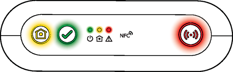
4. Green LED indicator
5. Yellow LED indicator
6. Red LED indicator
7. NFC [For Tunstall Use Only]
8. Back cover
9. Microphone
10. IR receiver [For Tunstall Use Only]
11. Speaker
Rear-view

1. On/Off (I/0) switch
2. Antenna connector
3. Ethernet/network connector (RJ45 port)
4. Power connector 12V (RJ11 port)
5. I/O port (Extended variant only)
6. Stub antenna
7. Cable slot
8. Security screw (T10) for battery slot
9. Battery slot
10. SIM card holder inside battery slot
11. 2x USB 2.0 ports [For Tunstall Use Only]
Installation and testing
This section describes how to install and test Lifeline Digital.
Installing Lifeline Digital
Remove and replace the back coverNote
Only remove the back cover for installation. The back cover protects the device from tampering.
To remove and replace the back cover:
1. Push and slide out the back cover to remove it (1).
2. Run all cables through the cable slot (2).
Replace the back cover when installation is completed (3).

Connect to mains power
Caution
Only use power adapters supplied by Tunstall.
1. Insert the power adaptor cable into the 12V connector on the device (1).
2. Connect the mains power adaptor into a wall socket (2).

Switch on Lifeline Digital
To switch on Lifeline Digital:
1. Set the On/OFF switch to 1 (ON) to power up the device (1).
The green and yellow LED indicators starts to flash rapidly to indicate startup progress.
The device is ready when the green LED remains solid and the yellow LED turns off.

Checking cellular signal strength
This section describes how to check cellular signal strength. This step is only required if you have concerns that cellular signal strength is poor.
Check cellular signal strength
To check cellular signal strength:
1. Press and hold the green Cancel button (1), then press and hold the red Alarm button (2) and the yellow Extra button (3).
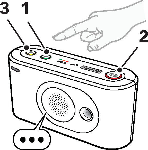
2. Release all buttons when the device emits a rising sound signal and announces "Programming mode”.
The LED indicators start chaser sequence and the button LEDs flash in unison to indicate that the programming mode is enabled.
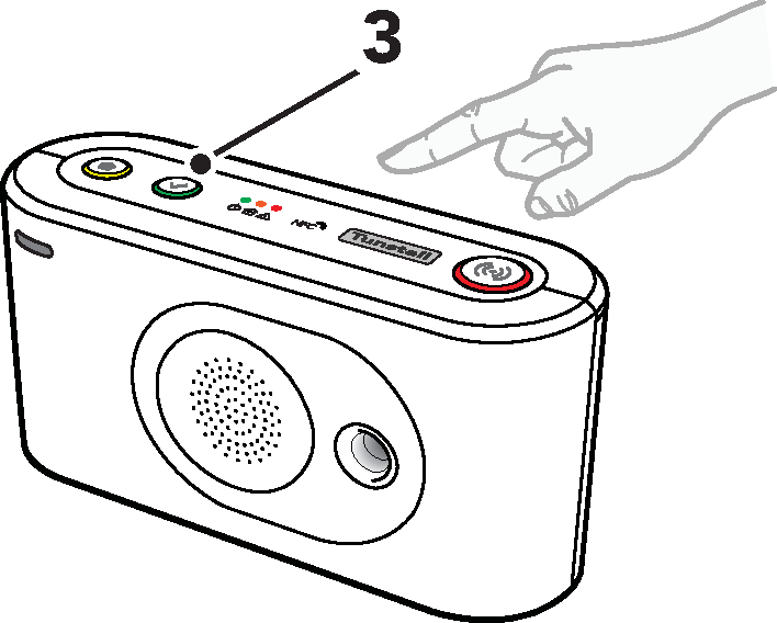
3. Press and hold the yellow Extra button (1).
4. When the device announces “Four”, release the button.
The device announces the current signal strength:
– “Cellular signal strength is One" for poor cellular signal strength.
– "Cellular signal strength is Two".
– "Cellular signal strength is Three".
– "Cellular signal strength is Four“.
– “Cellular signal strength is Five” for excellent cellular signal strength.
5. If necessary, adjust the position of the device to optimize cellular signal strength. If no suitable location can be found contact Tunstall for assistance.
6. Press the green Cancel button (3) to end the test and exit. The test automatically ends after 2 minutes.
Testing the installation
This section describes how to test the installation before the device can be considered ready for use.
Test alarm calls
To test alarm calls:
1. Press the pendant for 1-2 seconds to make an alarm call and the Care Consultant will confirm your details.
2. Activate any other connected alarm peripherals one by one and the Care Consultant will confirm the correct alarm information has been received.
Ready to use
Before the device can be considered ready for use:
• Make sure that all relevant tests of the device and associated equipment are completed
• Replace the back cover, see Remove and replace the back cover
• Make sure that the user and emergency contacts understand how to use Lifeline Digital and any associated equipment
Lifeline Digital is now ready to use.
Using Lifeline Digital
Some features may be configured differently than described in this document. Contact your supplier or Tunstall if you have any questions.
Alarm calls and alarm handling
The main functionality of Lifeline Digital is to distribute alarms and events to Tunstall’s Customer Care Centre. Alarms and events can be actively triggered by a user or passively by the system. Lifeline Digital distributes alarms and events according to pre-configured sequences to the Customer Care Centre. The type of alarm or event determines which sequence to use for distribution.
When an alarm call is initiated, the user can use Lifeline Digital as a speakerphone to communicate with the Customer Care Centre.
Make an alarm call
To make an alarm call:
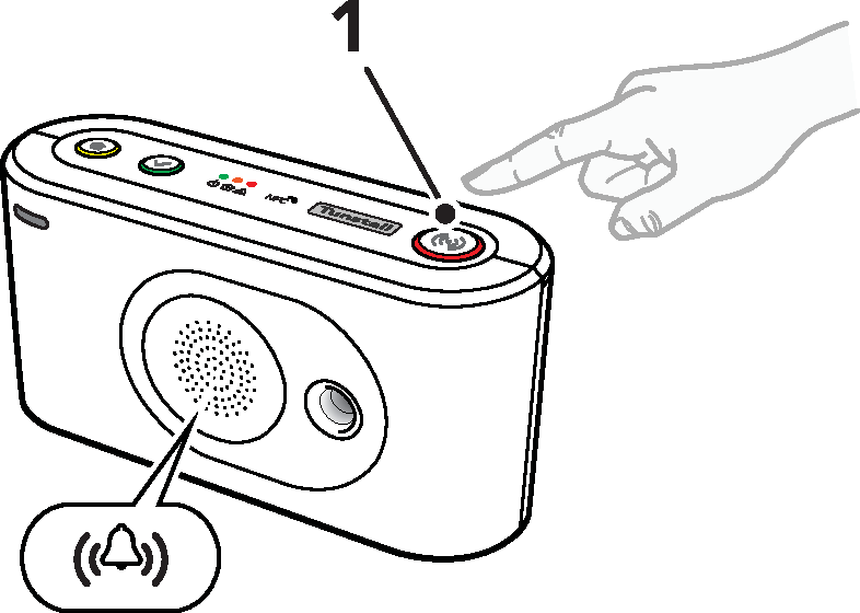
1. Press the red Alarm button (1) on the keypad.
Lifeline Digital announces "Alarm registered - Press the Cancel button to cancel the alarm - Do not worry, contacting assistance". The red Alarm button and the green LED indicator flash in unison when the device is calling the alarm receiver.
To make an alarm call using the TX4 button/pendant:
1. Press the push-button (2).
The red LED flashes to indicate that the alarm is transmitted to Lifeline Digital. The green LED flashes when the alarm is acknowledged by Lifeline Digital. Lifeline Digital announces "Alarm registered - Press the Cancel button to cancel the alarm - Do not worry, contacting assistance".

Alarm calls to the Customer Care Centre
When you have triggered an alarm call by pressing the button on Lifeline Digital or on the pendant, a voice connection to the Customer Care Centre is automatically established. A Care Consultant will answer your alarm call and speak to you via Lifeline Digital's speakerphone system.
• Tell the Care Consultant why you have generated the alarm call, and they will immediately arrange for assistance.
If you are unable to speak or hear, the Care Consultant will still arrange for assistance because the Customer Care Centre automatically knows that the alarm call is from you. The Customer Care Centre has all the information, such as your name and address, that is needed to help you quickly.
As soon as the Customer Care Centre ends the alarm call, Lifeline Digital is ready to make further alarm calls.
Cancel an alarm call
To prevent false alarms it is possible to cancel an alarm call before it is connected to the Customer Care Centre.
To cancel an alarm call:
1. When Lifeline Digital announces "Press the Cancel button to cancel the alarm", press the green Cancel button (1).
The device announces "The alarm has been cancelled".
If you do not cancel the alarm call in time, do not worry, our Customer Care Centre are always happy to hear from you.

System warnings
System warnings are visual (LED) and audio indications that notifies the care recipient or caregiver of power and connectivity errors.
System warning LED indications
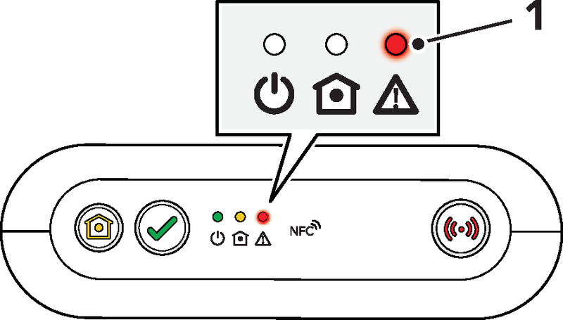
1. Red LED indicator
|
System warning indications 1/2 |
Status |
|
Red LED flashing x1 |
Ethernet failure |
|
Red LED flashing x2 |
Mains power failure |
|
Red LED flashing x3 |
Backup battery low |
|
Red LED flashing x4 |
Cellular modem failure |
|
Red LED flashing x5 |
Radio failure/interference |
[1] Feature must be enabled.
[2] Note that if several error conditions are present they are presented sequentially with a 2 second pause between indications. For example, two consecutive flashes followed by a pause and three consecutive flashes indicates that there is a mains failure and that the battery is low
System warning announcements

|
|||||||||||||||||||||||
|
|
Maintenance and cleaning
Power down Lifeline Digital
1. Remove the back cover, see Remove and replace the back cover.
2. Set the ON/OFF switch to 0 (OFF) to power down the device.
3. Disconnect all cables from the connection sockets.
4. Replace the back cover, see Remove and replace the back cover.
Cleaning and disinfecting Lifeline Digital
Do not use a wet cloth to clean Lifeline Digital. Do not use harsh, aggressive or corrosive cleaning agents to clean Lifeline Digital or the pendant. Take care not to allow moisture to get into Lifeline Digital's case or speaker openings when cleaning. Do not spray cleaning agents or disinfectants directly onto Lifeline Digital.
Disposal and recycling
When you no longer need the device, please contact Tunstall for instruction.
Disposal of batteries
This device contains rechargeable Lithium-ion batteries. Batteries must be disposed of in accordance with current local regulations. To avoid the risk of short circuiting, pack batteries separately or cover them with plastic tape before discarding or returning them.
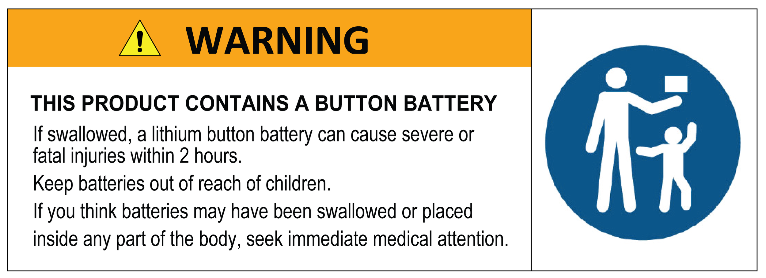
Warning
Keep batteries out of reach of children. Swallowing a battery can be life-threatening. Seek immediate medical attention if this happens.
Warning
Risk of explosion if battery is replaced by an incorrect type. Only use batteries from Tunstall. Dispose of used batteries according to current local regulations.
Battery information
All batteries should be disposed of in accordance with the latest legislation.
CAUTION: Do not ingest battery, chemical burn hazard.
The pendant with this product contains a coin/button cell battery. If the coin/button cell battery is swallowed, it can cause severe internal burns in just 2 hours and can lead to death. Keep new and used batteries away from children.
If the battery compartment is not closed securely, stop using the product and notify your supplier. If you think batteries might have been swallowed or placed inside any part of the body, seek immediate medical attention.
Button functions

1. Red Alarm button
2. Green Cancel button
3. Yellow Extra button
|
Mode |
Button |
Function |
|
Standby |
Press the red Alarm button |
Activate alarm/make alarm call |
|
Press the green Cancel button |
Cancel alarm Cancel system warning announcement |
|
|
Press and hold the green Cancel button for 3 seconds |
Trigger Online update (including configuration and firmware update) |
|
|
Press and hold the green Cancel button for 10 seconds |
Cancel all alarms and events in the distribution queue |
|
|
Press the yellow Extra button. |
Defers inactivity alarm and resets the basic inactivity timer (BIA) |
Button LEDs

1. Red Alarm button
2. Green Cancel button
3. Yellow Extra button
|
Indication |
Status |
|
Red LED on |
Standby mode |
|
Red LED flashing (0.5s on/4.5s off) |
Standby mode on backup battery |
|
Red LED flashing (0.5s on/0.5s off) |
Connection attempt |
|
Red LED flashing (1s on/1s off) |
Pausing between connection attempts |
|
Red LED flashing (0.5s on/4.5s off) |
No remaining connection attempts |
|
|
|
|
Yellow LED on |
Away mode |
|
Yellow LED flashing, (0.5 s on/ 4.5 s off) |
Away mode on backup battery |
|
|
|
|
Yellow LED flashing (0.5 s on/14.5 s off) |
Idle, waiting to restart Basic inactivity monitoring |
|
Yellow LED flashing (0.5 s on/9.5 s off) |
Basic inactivity monitoring active |
|
Yellow LED flashing (0.5 s on/ 0.5 s off) |
Sending basic inactivity alarm |
LED indicator status
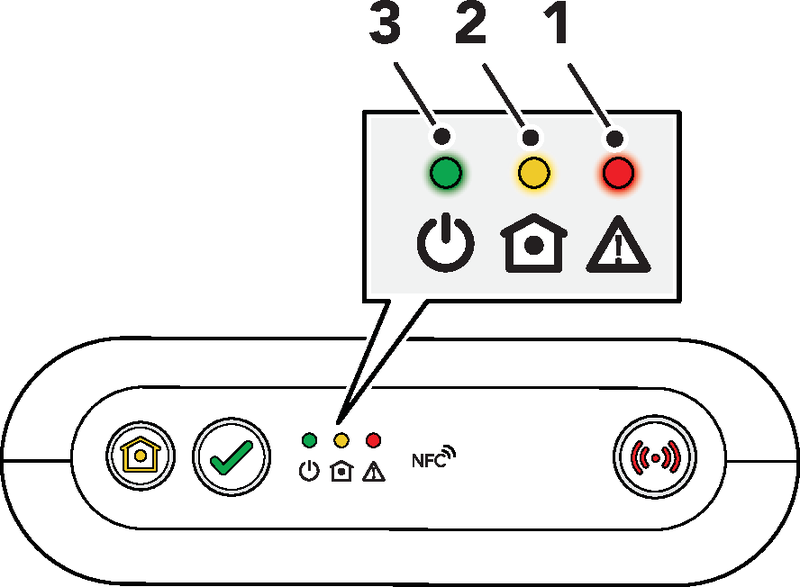
1. Red LED indicator
2. Yellow LED indicator
3. Green LED indicator
|
Indication |
Status |
|
Green LED on |
Standby mode |
|
Green LED flashing, (0.5 s on/ 4.5 s off) |
Standby mode on backup battery |
|
Green LED flashing (0.5 s on/ 0.5 s off) |
Connection attempt |
|
Green LED flashing (1 s on/1 s off) |
Pausing between connection attempts |
|
Green LED flashing (0.5 s on/ 4.5 s off) |
No remaining connection attempts |
|
Green LED rapid flashing4/5 |
Cellular modem initialization |
|
|
|
|
Yellow LED on |
Presence mode |
|
Yellow LED flashing (0.5 s on/ 2 s off) |
Presence mode on backup battery |
|
Yellow LED flashing (2 s on/ 2s off) |
Cancel At Source mode |
|
Yellow LED flashing (0.5 s on/ 4.5 s off) |
Cancel At Source mode on backup battery. |
|
Yellow LED flashing (0.5 s on/ 0.5 s off) |
Connection attempt to DMP |
|
Yellow LED flashing (1 s on/ 1 s off) |
Pausing between connection attempts to DMP |
|
Yellow LED rapid flashing |
Media processor starting up |
|
System warning indications |
Status |
|
Red LED flashing x1 |
Ethernet failure |
|
Red LED flashing x2 |
Mains power failure |
|
Red LED flashing x3 |
Backup battery low |
|
Red LED flashing x4 |
Cellular modem failure |
|
Red LED flashing x5 |
Radio failure/interference |
[4] Feature must be enabled.
[5] Note that if several error conditions are present they are presented sequentially with a 2 second pause between indications. For example, two consecutive flashes followed by a pause and three consecutive flashes indicates that there is a mains failure and that the battery is low
Technical data
Technical details Lifeline Digital
|
Weight |
491g net weight |
|
Dimensions |
180 x 58 x 98 mm (L x W x H) |
|
Mains power |
100-240v |
|
Backup battery |
Rechargeable Lithium-ion battery, 18Wh, 2500mAh capacity (continually internally charged) |
|
Backup time |
Up to 50 hours of stand-by operation with one 5-minute IPACS heartbeat and normal use (expected at date of purchase and when fully charged6) |
|
Radio frequencies |
AS/NZS: 917.6 MHz / 924 MHz |
|
Cellular |
4G - GSM/GPRS/LTE and VoLTE |
|
External connectivity |
SMA antenna connector, 2x USB 2.0 ports, Ethernet port (RJ45), 12V power inlet (RJ11) |
|
Integral connectivity |
NFC, Wi-Fi, 4G/LTE, Bluetooth Low Energy (BLE), Infrared receiver (IR) 2x SRD radio |
|
Environmental |
|
|
Operation temperature |
0°C to 55°C |
|
Storage temperature |
-20°C to +45°C max. 3 months storage |
|
Operation humidity |
0 to 90% RH, non-condensing |
|
Storage humidity |
0 to 95% RH, non-condensing |
|
Standard |
|
|
Safety |
AS/NZS 62368.1:2018 |
|
Radio |
AS/NZS 4268-2017 |
|
PERS |
AS4607:1999 |
|
EMC |
EN 301 489-1 V2.2.3 + Draft EN 301 489-17 V3.2.2 + Draft EN 301 489-3 V2.1.1 + Draft EN 301 489-52 V1.1.0 + EN 301 489-33/5. EN 55032:2015 + AC:2016 + EN 55035:2017 + EN 61000-3-2:2014 + EN 61000-3-3:2013. EN 50130-4:2011 + A1:2014 + EN 61000-6-3:2007 + A1:2011 + AC:2012. CISPR32:2015 + AC:2016 |
|
Design & manufacture |
ISO9001:2015 |
|
ROHS compliant |
2011/65/EU + 2015/863/EU |
[6] Time may be reduced by factors including temperature extremes, weak or intermittent cellular connectivity, high levels of sensor radio frequency activity and battery ageing.
Technical details TX4
|
Weight |
16g net weight (without attachments) |
|
Dimensions |
H 13mm, Ø 35 mm (without attachments) |
|
Battery |
3V Lithium CR2450 (replaceable) |
|
Battery lifetime |
Approx. 5 years |
|
Radio frequencies |
AS/NZS: 917.6 MHz |
|
Connection |
Bi-directional |
|
Range |
Minimum 25 meters indoors. Up to 250 meters outdoors. |
|
Water resistant |
Water resistant IP67 (water resistant to a depth of 1 meter for 30 minutes) |
|
Environmental |
|
|
Temperature |
+5°C to +40°C (Recommended) |
|
Standards |
|
|
Safety |
IEC 60950-1:2005, IEC 60950-1:2006+A11:2009+A1:2010+A12:2011 |
|
Radio |
AS/NZS 4268-2017 |
|
PERS |
AS4607:1999 |
|
EMC |
EN 55022:2010, EN 61000-3-2:2006, EN 61000-3-3:2008, EN61000-4-2,3,4,6,8,11, EN 301489-1, EN50130-4:2011 |
|
Design, manufacture, installation & service |
ISO9001:2015 |
|
Ingress protection (IP) |
IP67 |
Contact Details
New Zealand
Tunstall New Zealand Ltd
Business No. 3502431
PO Box 13153
Tauranga 3110
NEW ZEALAND
Telephone: 0800 488 678
Fax: 07 571 2685
Sales enquiries: nz.sales@tunstall.com
Support enquiries: nz.info@tunstall.com
Australia
Tunstall Australasia Pty Ltd
ABN 44 059 121 863
1/56 Lavarack Ave
Eagle Farm QLD 4009
Telephone: 1800 603 377
Fax: 1800 435 570
Sales enquiries: au.sales@tunstall.com
Support enquiries: au.info@tunstall.com
Our policy of continual development means that product specifications and appearance may change without notice.
Tunstall does not accept any responsibility for any errors and omissions contained within this document.
©2023 Tunstall Group Ltd.
®Tunstall and Lifeline Digital are trademarks